Arduino common modules/sensors

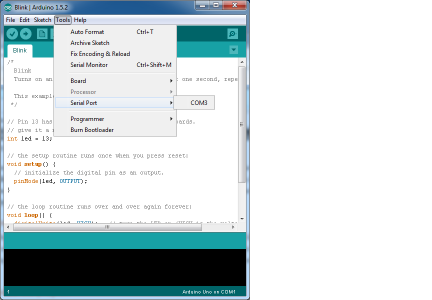
1. HC-SR04 Ultrasonic Module

The HC-SR04 ultrasonic sensor uses sonar to determine distance to an object like bats do. It offers excellent non-contact range detection with high accuracy and stable readings in an easy-to-use package.

1

2. IR Infrared Obstacle Avoidance Sensor Module

This module is very easy to use. When the module detects an obstacle in front of the signal , the green indicator light on the board level , while low-level continuous output signal OUT port , the module detects the distance 2 ~ 30cm, detection angle 35 °.

2

3. Soil Hygrometer Detection Module Soil Moisture Sensor

This is a simple water sensor can be used to detect soil moisture when the soil moisture deficit module outputs a high level, and vice versa output low. Use this sensor produced an automatic plant water device, so that the plants in your garden without people to manage.

3

4. Microphone Sensor


For sound detection Module has two outputs. AO, analog output, real-time output voltage signal of the microphone. DO, when the sound intensity reaches a certain threshold, the output high and low signal. The threshold-sensitivity can be adjusted via potentiometer on the sensor.

4

5. Digital Barometric Pressure Sensor Board

You can use this module to measure the absolute pressure of the environment. By converting the pressure measures into altitude, you have a reliable sensor for determining the height of your robot or projectile for example.

5

6. Photoresistor Sensor Module Light Detection Light

You can use this module for light detection with an Arduino.

6

7. Digital Thermal Sensor Module Temperature Sensor Module

The thermal sensor module is very sensitive to the ambient temperature, generally used to detect the ambient temperature. Through the adjustment of the potentiometer, you can change the temperature detection threshold.

7

8. Rotary Encoder Module Brick Sensor Development Board

When you rotate the rotary encoder it counts in the positive direction and the reverse direction. Rotation counts are not limited. With the buttons on the rotary encoder, you can reset to its initial state and start counting from 0.

8

9. MQ-2 MQ2 Gas Sensor Module Smoke Methane Butane Detection

This sensor module utilizes an MQ-2 as the sensitive component and has a protection resistor and an adjustable resistor on board. The MQ-2 gas sensor is sensitive to LPG, i-butane, propane, methane, alcohol, Hydrogen and smoke. It could be used in gas leakage detecting equipments in family and industry. The resistance of the sensitive component changes as the concentration of the target gas changes.

9


10. SW-420 Motion Sensor Module Vibration Switch Alarm

This module can be used to trigger the effect of various vibration, theft alarm, intelligent car, earthquake alarm, motorcycle alarm, etc.

10

11. Humidity and Rain Detection Sensor Module

This is a rain sensor. It’s used for all kinds of weather monitoring.

11

12. Passive Buzzer Module

A simple sound making module. You set high or low to drive this module by changing the frequency you’ll hear a different sound.

12

13. Speed Sensor Module

Tachometer is a simple module that allow you to test the speed of the motor. Widely used for motor speed detection, Pulse count, position limit, and so on.

14

14. IR Infrared Flame Detection Sensor Module

Flame Detection Sensor Module is sensitive to the flame, but also can detect ordinary light. Usually used as a flame alarm. Detects a flame or a light source of a wavelength in the range of 760nm-1100 nm. Detection point of about 60 degrees, particularly sensitive to the flame spectrum.

13

15. 5V 2-Channel Relay Module

This is a 2 Channel 5V Relay Module, it allows you to control various appliances, and other equipment with large current. It can be controlled directly by any microcontroller.15

16. Breadboard Power Supply Module 3.3V 5V

A simple module to power your breadboard. It supplies both 3.3V and 5V. View

16

17. HC-SR501 Pyroelectric Infrared Sensor Module

A PIR sensor is a little module that allows you to detect movement from humans or pets, it’s easy to integrate with your microcontroller.

17

18. Accelerometer Module

This module measures the acceleration. It’s commonly used in portable devices and video game controllers to detect movement and actions from the player. 18

19. DHT11 Temperature and Humidity Sensor

It’s a great little sensor to measure temperature and humidity from your room or outside. It integrates seamlessly with the Arduino.

dht-11

20 or 21. RF 433MHz Transmitter/Receiver

If you need data sent from one micro controller to another the 433MHz link modules are a cheap way to do that (all data is sent via Radio Frequency).

433 - Copy


Types of Arduino Boards

Types of Arduino Boards

There are different Arduino boards which are following

  • Arduino UNO (R3)
  • LilyPad Arduino
  • Red Board
  • Arduino Mega (R3)
  • Arduino Leonardo

Arduino UNO (R3)

The Arduino UNO R3 is a new board and by comparing with the previous Arduino boards it has some additional features. The Arduino UNO uses the Atmega16U2 instead of 8U2 and it allows faster transfer rate & more memory. There is no need of extra devices for the Linux & Mac and the ability to have the UNO show up as a keyboard, mouse, joystick, etc.

Arduino UNO

Arduino UNO

The Arduino R3 adds SDA & SCL pins which are next to the AREF and in addition, there are two pins which are placed near the RESET pin. The first pin is IOREF, it will allow the shields to adapt to the voltage from the board.

The other pin is not connected and it is reserved for the future purpose. The working of Arduino R3 is by all existing shields and it will adapt new shields which use these additional pins.

LilyPad Arduino

This board is an Arduino Programmable Microcontroller and it is designed to integrate easily into an e-textiles & wearable projects. The other Arduino boards have the same functionality like lightweight, round package designed to minimize snagging and profile, with wide tabs that can be sewn down and connected with conductive thread.

LilyPad Arduino Boards

LilyPad Arduino Boards

This Arduino board consist of an Atmega 328 with the Arduino bootloader and to keep it as a small minimum external component are required. The power supply of this board is 2V to 5V and offers large pin-out holes that make it easy to sew and connect. Each pin is connected to positive and negative terminals and to control the input & output devices like light, motor, and switch.

This Arduino technology was designed and developed by Leah Buechley and each LilyPad was creatively designed to have large connecting pads to allow them to be sewn into clothing. There is an available of various input, output, and sensor boards and they are washable.

Arduino Mega (R3)

The Arduino Mega is a type of Microcontroller and it is based on the ATmega2560. It consists of 54 digital input/output pins and from the total pins 14 pins are used for the PWM output, 16 pins are used for the analog inputs, 4 pins are used for the hardware serial port of the UART. There are pins like crystal oscillator of 16 MHz, USB connection, RESET pin, ICSP header, and a power jack.

Arduino Mega

Arduino Mega R3

This Arduino Mega is also having SDA and SCL pins which are next to the AREF. There are two new pins near the RESET pin which are IOREF that allow the shields to adapt to the voltage provided by the board. The other is a not connected and is reserved for future purposes.

Features of the Arduino Mega (R3)

  • ATmega2560 Microcontroller
  • Input voltage – 7-12V
  • 54 Digital I/O Pins (14 PWM outputs)
  • 16 Analog Inputs
  • 256k Flash Memory
  • 16Mhz Clock Speed

Arduino Leonardo

The Leonardo Arduino board is a Microcontroller board and it is based on the ATmega32u4 data sheet. This Arduino board has 20 digital input/out pins and from the total number of pins, seven pins are used for the pulse width modulation output and 12 pins are used as an analog input and there are the 16MHz crystal oscillator, a micro USB connection, RESET pin and power jack.

Arduino Leonardo

Arduino Leonardo

It contains everything needed to support the microcontroller; simply connect it to a computer with a USB cable or power it with an AC-to-DC adapter or battery to get started. The Leonardo differs from all preceding boards in that the ATmega32u4 has built-in USB communication, eliminating the need for a secondary processor.

This allows the Leonardo to appear to a connected computer as a mouse and keyboard, in addition to a virtual (CDC) serial COM port. It also has other implications for the behavior of the board; these are detailed on the getting started page.

Arduino Red Board

The Arduino red board is programmed by using the USB cable of mini-B with the help of Arduino IDE software.

Arduino Red Board

Arduino Red Board

Without any modifications in the security system there, it will work in Windows8 OS. The Arduino red board is more constant because USB and FTDI chips are used and they are flat on the back.

Creating it is very simple to utilize in the project design. Just plug the board, select the menu option to choose an Arduino UNO and you are ready to upload the program. You can control the RedBoard over USB cable using the barrel jack.

Installing Arduino IDE -MAC

Mac

This page will show you how to install and test the Arduino software on a Mac computer running OSX.

  • Go to the Arduino.cc and download the latest version of the Arduino software for Mac.
  • When the download is finished, un-zip it and open up the Arduino folder to confirm that yes, there are indeed some files and sub-folders inside. The file structure is important so don’t be moving any files around unless you really know what you’re doing.
  • Power up your Arduino by connecting your Arduino board to your computer with a USB cable (or FTDI connector if you’re using an Arduino pro). You should see the an LED labed ‘ON’ light up.
  • Move the Arduino application into your Applications folder.

FTDI Drivers

If you have an UNO, Mega2560, or Redboard, you shouldn’t need this step, so skip it!

  • For other boards, you will need to install drivers for the FTDI chip on your Arduino.
  • Go to the FTDI website and download the latest version of the drivers.
  • Once you’re done downloading, double click the package and follow the instructions from the installer.
  • Restart your computer after installing the drivers.

Launch and Blink!

After following the appropriate steps for your software install, we are now ready to test your first program with your Arduino board!

  • Launch the Arduino application
  • If you disconnected your board, plug it back in
  • Open the Blink example sketch by going to: File > Examples > 1.Basics > Blink

alt text

  • Select the type of Arduino board you’re using: Tools > Board > your board type

alt text

  • Select the serial port that your Arduino is attached to: Tools > Port > xxxxxx (it’ll probably look something like “/dev/tty.usbmodemfd131” or “/dev/tty.usbserial-131” but probably with a different number)

alt text

  • If you’re not sure which serial device is your Arduino, take a look at the available ports, then unplug your Arduino and look again. The one that disappeared is your Arduino.
  • With your Arduino board connected and the Blink sketch open, press the ‘Upload’ button

alt text

  • After a second, you should see some LEDs flashing on your Arduino, followed by the message ‘Done Uploading’ in the status bar of the Blink sketch.
  • If everything worked, the onboard LED on your Arduino should now be blinking! You just programmed your first Arduino!

How to Install Arduino Software and Drivers on Windows

Windows

This page will show you how to install and test the Arduino software with a Windows operating system (Windows 8, Windows 7, Vista, and XP).

Windows 8, 7, Vista, and XP

  • Go to the Arduino.cc page and download the latest version of the Arduino software for Windows.
  • When the download is finished, un-zip it and open up the Arduino folder to confirm that yes, there are indeed some files and sub-folders inside. The file structure is important so don’t be moving any files around unless you really know what you’re doing.
  • Power up your Arduino by connecting your Arduino board to your computer with a USB cable (or FTDI connector if you’re using an Arduino pro). You should see the an LED labed ‘ON’ light up.
  • If you’re running Windows 8, you’ll need to disable driver signing, so go see the Windows 8 section. If you’re running Windows 7, Vista, or XP, you’ll need to install some drivers, so head to the Windows 7, Vista, and XP section down below.

Windows 8,10

Windows 8 comes with a nice little security ‘feature’ that ‘protects’ you from unsigned driver installation. Some older versions of Arduino Uno come with unsigned drivers, so in order to use your Uno, you’ll have to tell Windows to disable driver signing. This issue has been addressed in newer releases of the Arduino IDE, but if you run into issues, you can try this fix first.


To temporarily disable driver signing:

  • From the Metro Start Screen, open Settings (move your mouse to the bottom-right-corner of the screen and wait for the pop-out bar to appear, then click the Gear icon)
  • Click ‘More PC Settings’
  • Click ‘General’
  • Scroll down, and click ‘Restart now’ under ‘Advanced startup’.
  • Wait a bit.
  • Click ‘Troubleshoot’.
  • Click ‘Advanced Options’
  • Click ‘Windows Startup Settings’
  • Click Restart.
  • When your computer restarts, select ‘Disable driver signature enforcement‘ from the list.

To permanently disable driver signing (recommended, but has some minor security implications):

  • Go to the metro start screen
  • Type in “cmd”
  • Right click “Command Prompt” and select “Run as Administrator” from the buttons on the bottom of your screen
  • Type/paste in the following commands: bcdedit -set loadoptions DISABLE_INTEGRITY_CHECKS bcdedit -set TESTSIGNING ON
  • Reboot!

Windows 7, Vista, and XP

Installing the Drivers for the Arduino Uno (from Arduino.cc)

  • Plug in your board and wait for Windows to begin it’s driver installation process
  • After a few moments, the process will fail, despite its best efforts
  • Click on the Start Menu, and open up the Control Panel
  • While in the Control Panel, navigate to System and Security. Next, click on System
  • Once the System window is up, open the Device Manager
  • Look under Ports (COM & LPT). You should see an open port named “Arduino UNO (COMxx)”. If there is no COM & LPT section, look under ‘Other Devices’ for ‘Unknown Device’

alt text

  • Right click on the “Arduino UNO (COMxx)” or “Unknown Device” port and choose the “Update Driver Software” option
  • Next, choose the “Browse my computer for Driver software” option

alt text

  • Finally, navigate to and select the Uno’s driver file, named “ArduinoUNO.inf”, located in the “Drivers” folder of the Arduino Software download (not the “FTDI USB Drivers” sub-directory). If you cannot see the .inf file, it is probably just hidden. You can select the ‘drivers’ folder with the ‘search sub-folders’ option selected instead.
  • Windows will finish up the driver installation from there


Launch and Blink!

After following the appropriate steps for your software install, we are now ready to test your first program with your Arduino board!

  • Launch the Arduino application
  • If you disconnected your board, plug it back in
  • Open the Blink example sketch by going to: File > Examples > 1.Basics > Blink

alt text

  • Select the type of Arduino board you’re using: Tools > Board > your board type

alt text

  • Select the serial/COM port that your Arduino is attached to: Tools > Port > COMxx

alt text

  • If you’re not sure which serial device is your Arduino, take a look at the available ports, then unplug your Arduino and look again. The one that disappeared is your Arduino.
  • With your Arduino board connected, and the Blink sketch open, press the ‘Upload’ button

alt text

  • After a second, you should see some LEDs flashing on your Arduino, followed by the message ‘Done Uploading’ in the status bar of the Blink sketch.
  • If everything worked, the onboard LED on your Arduino should now be blinking! You just programmed your first Arduino!

Controlling LED using Bluetooth Module – Arduino

Ever thought of controlling any of your electronic devices with your smart phone? How about a robot or any other device? Wouldn’t it be cool to control them with your smartphone? Here is a simple tutorial for interfacing an Android Smartphone with Arduino via Bluetooth!

Required Materials

arduino bluetooth

Hardware

  1. Bluetooth Module HC 05/06
  2. Arduino& Battery (with cable)
  3. LED
  4. 220 OHM Resistor
  5. Android device

Software

  1. Arduino IDE
  2. Android Studio.

Android studio isn’t really required here since I will provide you with the android application that I made. You can install the given .apk file to use the application. 🙂

How Does it Work?

There are three main parts to this project. An Android smartphone, a Bluetooth transceiver, and an Arduino.

arduino bluetooth

HC 05/06 works on serial communication. The Android app is designed to send serial data to the Arduino Bluetooth module when a button is pressed on the app. The Arduino Bluetooth module at other end receives the data and sends it to the Arduino through the TX pin of the Bluetooth module(connected to RX pin of Arduino). The code uploaded to the Arduino checks the received data and compares it. If the received data is 1, the LED turns ON. The LED turns OFF when the received data is 0. You can open the serial monitor and watch the received data while connecting.

Connecting the Arduino Bluetooth hardware

arduino bluetooth

This circuit is simple and small. There are only four connections to be made between the Arduino and Bluetooth module!!

Arduino Pins Bluetooth Pins

RX (Pin 0) ———> TX

TX (Pin 1) ———> RX

5V ———> VCC

GND ———> GND

Connect a LED positive to pin 13 of the Arduino through a resistance (valued between 220Ω – 1KΩ). Connect its negative to GND, and you’re done with the circuit!


arduino bluetooth

Note: Don’t Connect RX to RX and TX to TX on the Bluetooth and Arduino. You will receive no data. Here TX means Transmit and RX means Receive.

Uploading the Sketch to Arduino


char data = 0; //Variable for storing received data
void setup()
{
Serial.begin(9600); //Sets the data rate in bits per second (baud) for serial data transmission
pinMode(13, OUTPUT); //Sets digital pin 13 as output pin
}
void loop()
{
if(Serial.available() > 0) // Send data only when you receive data:
{
data = Serial.read(); //Read the incoming data and store it into variable data
Serial.print(data); //Print Value inside data in Serial monitor
Serial.print("\n"); //New line
if(data == '1') //Checks whether value of data is equal to 1
digitalWrite(13, HIGH); //If value is 1 then LED turns ON
else if(data == '0') //Checks whether value of data is equal to 0
digitalWrite(13, LOW); //If value is 0 then LED turns OFF
}

}

Upload the given sketch to Arduino using the Arduino IDE software, you can also get it from Github.

Installing the Android Application

arduino bluetooth

In this tutorial, I will not cover Android app development. You can download the android application from here and the source code of the entire project.

  • Download the Application from Amazon App Store or Github
  • Pair your device with the HC 05/06 Bluetooth module:
  • 1. Turn ON the HC 05/06 Bluetooth module by powering the Arduino.
  • 2. Scan your smartphone for available devices.
  • 3. Pair your smartphone to the HC 05/06 by entering default password 1234 OR 0000.
  • Install the LED application on your Android device.
  • Open the Application

arduino bluetooth

  • Press paired devices
  • Select your Bluetooth module from the List (HC-05/06)

  • After connecting successfully, press the ON button to turn the LED on and the OFF button to turn the LED off.
  • Disconnect the button to disconnect Bluetooth module.

Custom Character LCD

We can generate a completely different style of the custom character using the below pixel array shown in the image.

the custom character shown below that is used in our program to generate the smile type character:

{

0b00000,

0b00000,

0b01010,

0b00000,

0b10001,

0b01110,

0b00000,

0b00000

};

Circuit diagram:

Source Code :

#include <LiquidCrystal.h>  LiquidCrystal lcd(12,11,5,4,3,2); // make some custom characters:  byte heart[8] = { 0b00000, 0b01010,                    0b11111, 0b11111,                    0b11111, 0b01110,                    0b00100, 0b00000                   };  byte smile[8] = { 0b00000, 0b00100,                   0b10010, 0b00001,                   0b10001, 0b00010,                   0b00100, 0b00000                   };  void setup() {      lcd.createChar(1, heart);     lcd.createChar(2, smile);     lcd.begin(16, 2);      //lcd.clear();      lcd.print("I ");     lcd.write(1);     lcd.print(" U");     lcd.write(2); }  void loop() {     lcd.setCursor(0,1);     lcd.print(millis()/1000); }

All done!!

Arduino LCD

In this Arduino LCD Tutorial we will learn how to connect an LCD (Liquid Crystal Display) to the Arduino board. LCDs like these are very popular and broadly used in electronics projects as they are good for displaying information like sensors data from your project, and also they are very cheap.

The LCD Pinout


It has 16 pins and the first one from left to right is the Ground pin. The second pin is the VCC which we connect the 5 volts pin on the Arduino Board. Next is the Vo pin on which we can attach a potentiometer for controlling the contrast of the display.

Next, The RS pin or register select pin is used for selecting whether we will send commands or data to the LCD. For example if the RS pin is set on low state or zero volts, then we are sending commands to the LCD like: set the cursor to a specific location, clear the display, turn off the display and so on. And when RS pin is set on High state or 5 volts we are sending data or characters to the LCD.

LCD Pin-Out

Next comes the R / W pin which selects the mode whether we will read or write to the LCD. Here the write mode is obvious and it is used for writing or sending commands and data to the LCD. The read mode is used by the LCD itself when executing the program which we don’t have a need to discuss about it in this tutorial.

Next is the E pin which enables the writing to the registers, or the next 8 data pins from D0 to D7. So through this pins we are sending the 8 bits data when we are writing to the registers or for example if we want to see the latter uppercase A on the display we will send 0100 0001 to the registers according to the ASCII table.

And the last two pins A and K, or anode and cathode are for the LED back light.

After all we don’t have to worry much about how the LCD works, as the Liquid Crystal Library takes care for almost everything. From the Arduino’s official website you can find and see the functions of the library which enable easy use of the LCD. We can use the Library in 4 or 8 bit mode. In this tutorial we will use it in 4 bit mode, or we will just use 4 of the 8 data pins.

Components needed for this Arduino LCD Tutorial


  • 16×2 Character LCD………………
  • Arduino Board………………………
  • Potentiometer………………………
  • Breadboard and Jump Wires…

Circuit Schematic


We will use just 6 digital input pins from the Arduino Board. The LCD’s registers from D4 to D7 will be connected to Arduino’s digital pins from 4 to 7. The Enable pin will be connected to pin number 2 and the RS pin will be connected to pin number 1. The R/W pin will be connected to Ground and the Vo pin will be connected to the potentiometer.

LCD Circuit Schematic

Source Codes


First thing we need to do is it insert the Liquid Crystal Library. We can do that like this: Sketch > Include Library > Liquid Crystal. Then we have to create an LC object. The parameters of this object should be the numbers of the Digital Input pins of the Arduino Board respectively to the LCD’s pins as follow: (RS, Enable, D4, D5, D6, D7). In the setup we have to initialize the interface to the LCD and specify the dimensions of the display using the begin() function.

In the loop we write our main program. Using the print() function we print on the LCD. The setCursor() function is used for setting the location at which subsequent text written to the LCD will be displayed. The blink() function is used for displaying a blinking cursor and the noBlink() function for turning off. The cursor() function is used for displaying underscore cursor and the noCursor() function for turning off. Using the clear() function we can clear the LCD screen.

/*
* Arduino LCD Tutorial
*
* Crated by vaishnav.a
* www.antlem.tk
*
*/

#include <LiquidCrystal.h> // includes the LiquidCrystal Library
LiquidCrystal lcd(1, 2, 4, 5, 6, 7); // Creates an LC object. Parameters: (rs, enable, d4, d5, d6, d7)

void setup() {
lcd.begin(16,2); // Initializes the interface to the LCD screen, and specifies the dimensions (width and height) of the display }
}

void loop() {
lcd.print(“Arduino”); // Prints “Arduino” on the LCD
delay(3000); // 3 seconds delay
lcd.setCursor(2,1); // Sets the location at which subsequent text written to the LCD will be displayed
lcd.print(“LCD Tutorial”);
delay(3000);
lcd.clear(); // Clears the display
lcd.blink(); //Displays the blinking LCD cursor
delay(4000);
lcd.setCursor(7,1);
delay(3000);
lcd.noBlink(); // Turns off the blinking LCD cursor
lcd.cursor(); // Displays an underscore (line) at the position to which the next character will be written
delay(4000);
lcd.noCursor(); // Hides the LCD cursor
lcd.clear(); // Clears the LCD screen
}

All done…

Arduino – led Multiple Blinks

The Scheduler library allows the Arduino Due to manage multiple tasks at the same time. By setting up a number of other functions that run the same way loop() does, it’s possible to have separate looping functions without a dedicated timer.

Hardware Required
  • Arduino Due Board
  • three LEDs
  • three 220 ohm resistors

The Circuit

The anode of the LEDs are connected in series with a 220-ohm resistor to pins 11, 12, and 13 on the Due. Their cathodes connect to ground.

Code

// Include Scheduler since we want to manage multiple tasks.
#include <Scheduler.h>int led1 = 12;
int led2 = 10;
int led3 = 8;

void setup() {
Serial.begin(9600);

// Setup the 3 pins as OUTPUT
pinMode(led1, OUTPUT);
pinMode(led2, OUTPUT);
pinMode(led3, OUTPUT);

// Add “loop2” and “loop3” to scheduling.
// “loop” is always started by default.
Scheduler.startLoop(loop2);
Scheduler.startLoop(loop3);
}

// Task no.1: blink LED with 1 second delay.
void loop() {
digitalWrite(led1, HIGH);

// IMPORTANT:
// When multiple tasks are running ‘delay’ passes control to
// other tasks while waiting and guarantees they get executed.
delay(1000);

digitalWrite(led1, LOW);
delay(1000);
}

// Task no.2: blink LED with 0.1 second delay.
void loop2() {
digitalWrite(led2, HIGH);
delay(100);
digitalWrite(led2, LOW);
delay(100);
}

// Task no.3: accept commands from Serial port
// ‘0’ turns off LED
// ‘1’ turns on LED
void loop3() {
if (Serial.available()) {
char c = Serial.read();
if (c==‘0’) {
digitalWrite(led3, LOW);
Serial.println(“Led turned off!”);
}
if (c==‘1’) {
digitalWrite(led3, HIGH);
Serial.println(“Led turned on!”);
}
}

// IMPORTANT:
// We must call ‘yield’ at a regular basis to pass
// control to other tasks.
yield();
}

Arduino Blink

STEP 1: THE CIRCUIT

First, connect pin 7 on your Arduino to a spot on your breadboard, then your resistor. On the other side of the resistor, insert your LED.

NOTE: LEDs are polarised, meaning that they have a certain way they need to be connected if you are to not blow them. Connect the positive lead of the LED to the resistor and run a wire from the ground lead to the GND pin on the Arduino. The result should look like the schematic on this tutorial.

STEP 2: THE CODE

Now for the coding half. This is where the real magic of Arduino happens. This little blue board can be programmed to do almost anything you can think up. The code we need to write for this is fairly simple, but first you need to download the Arduino IDE from their website.

To begin, you want to set up your IDE for writing your code. Every Arduino program needs these two things for it to work. Start by writing this:

void setup() {
}
void loop() {
}

How this works is that when you reset your Arduino or boot it up, the code within the ‘void setup’ section is run. Once that is finished, ‘void loop’ gets run over and over until power is removed from the Arduino. Before your ‘void setup’ though, we want to assign pin seven a name so that we know what we are controlling on it later one. Write before ‘void setup’:

int led = 7;

This assigns the name ‘led’ the integer 7. Now every time we write ‘led’ in our code, Arduino will interpret that as 7. Within your ‘void setup’, we want to write a line of code that will let the Arduino know that we want pin 7, or led, to act as an output. An output is a pin that is either HIGH or LOW, meaning it is either ON or OFF. But we don’t need to worry about that just yet. Just remember that an OUTPUT gives out electricity, and INPUT collects information from pins. After void setup() {, write:

pinMode(led, OUTPUT);

Keep in mind that it is very important that each line ends with a semicolon.
Now for the actual controlling of the LED. After void loop() {, write the following:

digitalWrite(led, HIGH);

This will set pin 7 HIGH, or ON, meaning that while it is high it is outputting voltage. If you ran your code now, the LED would light up and stay lit. Give it a try if you want. But the point of this tutorial was to make the LED blink, was it not? On the next line, write “delay(1000);”
This will make the Arduino pause for a full second. If you wanted it to be half a second, write 500 instead of 1000. You can make this number anything you want. But it still doesn’t blink.
On the line after that, write:

digitalWrite(led, LOW);

This turns your LED off after the period you set it to delay. Run your code now. Notice anything strange? It still doesn’t blink! Give it some thought and see if you can work it out yourself, keeping in mind what i’ve told you about the void loop function.

Worked it out?

Don’t worry if you didn’t, it could be confusing. Also if you didn’t even try well then you my friend are mean 😛
Anyway, the reason is because it is looping as soon as it reaches the line that turns the LED off, going right back to where it turns on. There isn’t any time for you to observe the LED being off. The solution? Add another delay line after you turn the LED off. Hey presto, you have a blinking LED!

Your final code should look like as follows:

int led = 7;
void setup() {
pinMode(led, OUTPUT);
}

void loop() {
digitalWrite(led, HIGH);
delay(1000);
digitalWrite(led, LOW);
delay(1000);
}

STEP 3: GOING FURTHER

Using what we spoke about with integers, you could create something a little more interesting, like altering the code for the delay as such:

int led = 7;
int del = 1000;

void setup() {
pinMode(led, OUTPUT);
}

void loop() {
digitalWrite(led, HIGH);
delay(del);
digitalWrite(led, LOW);
delay(del);
}

This is simply replacing the number 1000 with a stored integer. You can use this to your advantage in many different ways. I won’t explain the following code, you can work out how it is working for yourself, but it is just one example of the endless possibilities.

int led = 7;
int del = 5000;

void setup() {
pinMode(led, OUTPUT);
}

void loop() {
digitalWrite(led, HIGH);
delay(del);
digitalWrite(led, LOW);
delay(del);
del = del – 100;
}

What is Arduino?

arduino_board
Arduino is an open source electronics platform accompanied with a hardware and software to design, develop and test complex electronics prototypes and products. The hardware consists of a microcontroller with other electronic components which can be programmed using the software to do almost any task. The simplicity of the Arduino language makes it very easy for almost everyone who has an interest in electronics to write programs without the understanding of complex algorithms or codes.
Arduino is intended for an artist, tinker, designer or anyone, interested in playing with electronics without the knowhow of complex electronics and programming skills. Arduino is an excellent designed open source platform. It has specially designed boards which can be programmed using the Ardunio Programming Language (APL).
The presence of Arduino is not only spreading between hobbyists, but it has also expanded its roots in industries and used by experts for making prototypes of commercial products. Arduino takes off the efforts required in complex coding and designing hardware.
 
The open source nature of Arduino has been the main reason for its rapid horizontal growth. Since it is an Open Source project, all the files related to hardware and software is available for personal or commercial use. The development cost of the hardware is very small as against the costly similar proprietary products by the industrial giants. The open source nature doesn’t require any licenses to develop, use, redistribute or even sell the product. But the Arduino name is trade mark protected (Arduino™) i.e., you are free to sell the Arduino board under any other name however in order to sell it under the name “Arduino” you need to take permission from the founders and follow their quality terms.
The Software files which includes all the source code library are also open sourced. A user can modify them to make the project more versatile and improve its capabilities. This provides a strong online community support.

Concept of Arduino

The root of Arduino goes deep down to the development of Processing Language by MIT researchers. Processing language is an open source language designed to introduce the software development environment for the artistic people without the need of deep knowledge of programming of algorithms. Processing is based on java.
In early year of 21st century, designing an electronics gadget was nearly impossible for a common man. The requirement of specific skill set and hefty prices of software and hardware created a full stop in the path of their creativity.
In year 2003 Hernando Barragan, a programmer developed an open source electronics development platform with software IDE, where anyone with a small knowledge in electronics and programming could use his project to give wings to their creativity. His focus was to reduce the burden of complexity in designing electronics hardware and software. The project was named as Wiring. The software IDE of the Wiring used processing language to write the codes.
As the program written in C\C++ is named as Project, in the same way the code written in Wiring (even in Processing and Arduino) is termed as Sketch. The name sketch gives a familiar look for an artist.
The principle idea behind Wiring is that one can make the sketch of their idea on Wiring software and implement it using specially designed Wiring board. You need to write a few lines of codes on the software IDE and then download the program to the onboard microcontroller to see the output.
Wiring has predefined libraries to make the programming language easy. Arduino uses these libraries. The predefined libraries are written in C and C++. One can even write his software in C\C++ and use them on Wiring boards. The difference between writing a program in C/C++ and Wiring is that the Wiring Application Programmable Interface (API) has simplified programming style and the user doesn’t require detailed knowledge of the concepts like classes, objects, pointers, etc. While sketching hardware you need to call the predefined functions and rest will be handled by the Wiring software.
The basic difference between the Processing and the Wiring is that the Processing is use to write the program which can be used on other computers while Wiring program is used on microcontrollers.