In this Arduino LCD Tutorial we will learn how to connect an LCD (Liquid Crystal Display) to the Arduino board. LCDs like these are very popular and broadly used in electronics projects as they are good for displaying information like sensors data from your project, and also they are very cheap.
The LCD Pinout
It has 16 pins and the first one from left to right is the Ground pin. The second pin is the VCC which we connect the 5 volts pin on the Arduino Board. Next is the Vo pin on which we can attach a potentiometer for controlling the contrast of the display.
Next, The RS pin or register select pin is used for selecting whether we will send commands or data to the LCD. For example if the RS pin is set on low state or zero volts, then we are sending commands to the LCD like: set the cursor to a specific location, clear the display, turn off the display and so on. And when RS pin is set on High state or 5 volts we are sending data or characters to the LCD.

Next comes the R / W pin which selects the mode whether we will read or write to the LCD. Here the write mode is obvious and it is used for writing or sending commands and data to the LCD. The read mode is used by the LCD itself when executing the program which we don’t have a need to discuss about it in this tutorial.
Next is the E pin which enables the writing to the registers, or the next 8 data pins from D0 to D7. So through this pins we are sending the 8 bits data when we are writing to the registers or for example if we want to see the latter uppercase A on the display we will send 0100 0001 to the registers according to the ASCII table.
And the last two pins A and K, or anode and cathode are for the LED back light.
After all we don’t have to worry much about how the LCD works, as the Liquid Crystal Library takes care for almost everything. From the Arduino’s official website you can find and see the functions of the library which enable easy use of the LCD. We can use the Library in 4 or 8 bit mode. In this tutorial we will use it in 4 bit mode, or we will just use 4 of the 8 data pins.
Components needed for this Arduino LCD Tutorial
- 16×2 Character LCD………………
- Arduino Board………………………
- Potentiometer………………………
- Breadboard and Jump Wires…
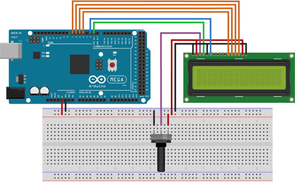
Circuit Schematic
We will use just 6 digital input pins from the Arduino Board. The LCD’s registers from D4 to D7 will be connected to Arduino’s digital pins from 4 to 7. The Enable pin will be connected to pin number 2 and the RS pin will be connected to pin number 1. The R/W pin will be connected to Ground and the Vo pin will be connected to the potentiometer.
Source Codes
First thing we need to do is it insert the Liquid Crystal Library. We can do that like this: Sketch > Include Library > Liquid Crystal. Then we have to create an LC object. The parameters of this object should be the numbers of the Digital Input pins of the Arduino Board respectively to the LCD’s pins as follow: (RS, Enable, D4, D5, D6, D7). In the setup we have to initialize the interface to the LCD and specify the dimensions of the display using the begin() function.
In the loop we write our main program. Using the print() function we print on the LCD. The setCursor() function is used for setting the location at which subsequent text written to the LCD will be displayed. The blink() function is used for displaying a blinking cursor and the noBlink() function for turning off. The cursor() function is used for displaying underscore cursor and the noCursor() function for turning off. Using the clear() function we can clear the LCD screen.
/*
* Arduino LCD Tutorial
*
* Crated by vaishnav.a
* www.antlem.tk
*
*/
#include <LiquidCrystal.h> // includes the LiquidCrystal Library
LiquidCrystal lcd(1, 2, 4, 5, 6, 7); // Creates an LC object. Parameters: (rs, enable, d4, d5, d6, d7)
void setup() {
lcd.begin(16,2); // Initializes the interface to the LCD screen, and specifies the dimensions (width and height) of the display }
}
void loop() {
lcd.print(“Arduino”); // Prints “Arduino” on the LCD
delay(3000); // 3 seconds delay
lcd.setCursor(2,1); // Sets the location at which subsequent text written to the LCD will be displayed
lcd.print(“LCD Tutorial”);
delay(3000);
lcd.clear(); // Clears the display
lcd.blink(); //Displays the blinking LCD cursor
delay(4000);
lcd.setCursor(7,1);
delay(3000);
lcd.noBlink(); // Turns off the blinking LCD cursor
lcd.cursor(); // Displays an underscore (line) at the position to which the next character will be written
delay(4000);
lcd.noCursor(); // Hides the LCD cursor
lcd.clear(); // Clears the LCD screen
}
All done…
